Project motivation
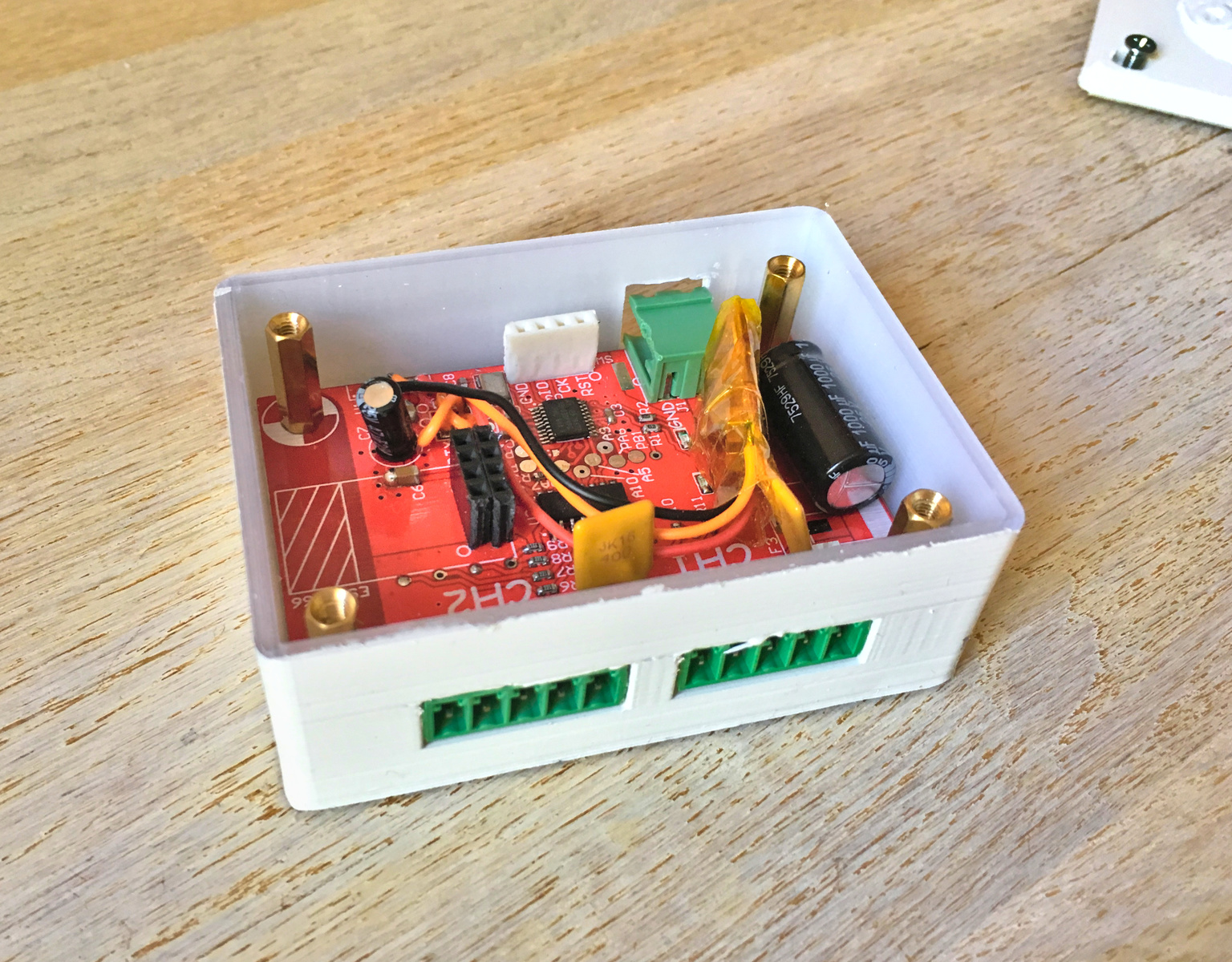 The completed driver board installed in the 3D-printed case. This device can now be connected to
12V and two segments of LED tape that can then be controlled trough Wifi. The ESP8266 module goes on the pin
header on the left and was removed for this picture.
The completed driver board installed in the 3D-printed case. This device can now be connected to
12V and two segments of LED tape that can then be controlled trough Wifi. The ESP8266 module goes on the pin
header on the left and was removed for this picture.
After the multichannel LED driver was completed, I was just getting used to controlling LEDs at 14-bit resolution.
I liked the board we designed in this project, but at 32 channels it was a bit large for most use cases. Sometimes I
just want to pop a piece of LED tape or two somewhere, but I don't need a full 32 channels of control. I ended up
thinking that a smaller version of the 32-channel driver that didn't require a separate control computer would be
handy. So I sat down and designed a variant of the design with only 8 channels instead of 32 and an on-board ESP8266
module instead of the RS485 transceiver for WiFi connectivity.
The Electronics
The schematic was mostly copy-pasted from the 32-channel design. The PCB was designed from scratch. This time, I went
for a 5x7cm form factor to allow for enough room for all connectors and to give the ESP8266's WiFi antenna enough
space. The board has two 5-pin Phoenix-style for two RGB-White (RGBW) tapes and one 2-pin Phoenix-style connector for
12V power input. The control circuitry and the serial protocol are unchanged, but the STM32 now talks to an ESP-01
module running custom firmware.
The LEDs are driven using a 74HC595 shift register controlling a bunch of AO3400 MOSFETs, with resistors in front of
the MOSFETs' gates to slow down the transitions a bit to reduce brighntess nonlinearities and EMI resulting from
ringing of the LED tape's wiring inductance.
The board has two spots for either self-resettable fuses (polyfuses) or regular melting-wire fuses in
a small SMD package, one for each RGBW output. For low currents the self-resettable fuses should be okay but at higher
currents their trip times get long enough that they become unlikely to trip in time to save anything, so plain old non-resettable fuses would be the way to go there.
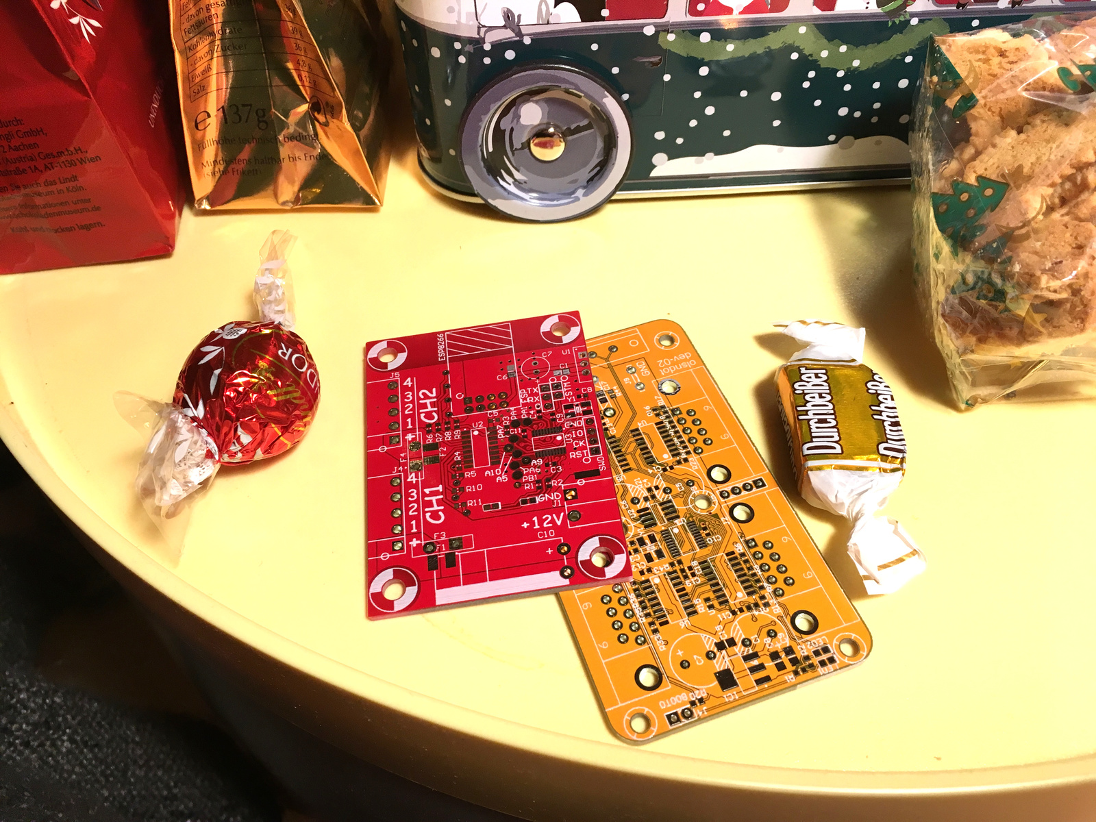 The completed PCBs of this project (front) and the `multichannel LED driver`_ project the driver
circuitry was derived from (back).
The completed PCBs of this project (front) and the `multichannel LED driver`_ project the driver
circuitry was derived from (back).
The Firmware
The STM32 firmware only had to be slightly modified to accomodate the reduced channel count since the protocol remains
unchanged. The ESP firmware is based on esphttpd by Spritetm. The modifications to the webserver firmware are pretty
basic. First, the UART console has been disabled since I use the UART to talk to the STM32. The few bootloader messages
popping out the UART on boot are not an issue, since they're unlikely to contain the fixed 32-bit address prefix the
serial protocol requires for the STM32 to do anything.
Second, I added LED control by adding drivers for the serial protocol and a bunch of colorspace conversion functions.
When I first tested the prototype software, I noticed that color reproduction was extremely poor. When I just sent a
HSV rainbow fade from a python command line, the result looked totally wrong. The fade did not seem to go at a constant
speed and some colors, in particular yellow, orange and greens, were not visible at all. The problem turned out to be a
stark mismatch of the red, green and blue channels of the LED tape and less-than-optimal color reproduction of the pure
colors. I decided to properly measure the LED tape's color reproduction so I could compensate for it in software. This
turned out to be an extremely interesting project, the details of which you can read in my LED characterization
article.
Third, I updated the built-in websites with some ad-hoc documentation on how to use the thing and a basic interface for
LED control.
Making an enclosure
To be actually useful, the driver needed a robust enclosure. Bare PCBs are nice for prototyping, but for actually
putting the thing anywhere it needs a case to protect it against random destruction.
The board has four mounting holes with comfortable spacing in its corners to allow easy mounting inside a 3D-printed
case. The case itself is described in an OpenSCAD script. To make it look a little nicer, a little 3D relief is laid
into the lid. The 3D relief is generated with a bit of blender magic. The source STL model is loaded into blender, then
blender's amazingly flexible rendering system is used to export a depth map of a projection of the model as a PNG file.
This depth map is then imported as a triangle mesh into OpenSCAD.
For the relief to look good, I chose a rather high resolution for the depth map. This unfortunately leads to extreme
memory use and processing time on the part of OpenSCAD, but since I have access to a sufficiently fast machine that is
not a problem. Just be careful if you try opening the OpenSCAD file on your machine, OpenSCAD will probably crash
unless you're on a beefy machine or interrupt it when it starts auto-rendering the file.
The board is mounted into the enclosure using knurled insert nuts that are pressed into a 3D-printed hole using a bit of
violence.