32-Channel LED tape driver

2018-05-02

Theoretical basics

Together, a friend and I outfitted the small staircase at Berlin's Chaos Computer Club with nice, shiny RGB-WW LED tape for ambient lighting. This tape is like regular RGB tape but with an additional warm white channel, which makes for much more natural pastels and whites. There are several variants of RGBW tape. Cheap ones have separate RGB and white LEDs, which is fine for indirect lighting but does not work for direct lighting. Since we wanted to mount our tape in channels at the front of the steps, we had to use the slightly more expensive variant with integrated RGBW LEDs. These are LEDs in the 5050 (5.0mm by 5.0mm) form factor common with RGB LEDs that have a small section divided off for the white channel. The red, green and blue LED chips sit together in the larger section covered with clear epoxy and the white channel is made up from the usual blue LED inside a yellow phosphor in the smaller section.

Since we wanted to light up all of 15 steps, and for greatest visual effect we would have liked to be able to control each step individually we had to find a way to control 60 channels of LED tape with a reasonable amount of hardware.

LED tape has integrated series resistors and runs off a fixed 12V or 24V constant-voltage supply. This means you don't need a complex constant-current driver as you'd need with high-power LEDs. You can just hook up a section of LED tape to a beefy MOSFET to control it. Traditionally, you would do Pulse Width Modulation (PWM) on the MOSFET's input to control the LED tape's brightness.

Pulse Width Modulation

Pulse Width Modulation is a technique of controlling the brightness of a load such as an LED with a digital signal. The basic idea is that if you turn the LED on and off much too fast for anyone to notice, you can control its power by changing how long you turn it on versus how long you leave it off.

PWM divides each second into a large number of periods. At the beginning of each period, you turn the LED on. After that, you wait a certain time until you turn it off. Then, you wait for the next period to begin. The periods are always the same length but you can set when you turn off the LED. If you turn it off right away, it's off almost all the time and it looks like it's off to your eye. If you turn it off right at the end, it's on almost all the time and it looks super bright to your eye. Now, if you turn it off halfway into the cycle, it's on half the time and it will look to your eye as half as bright as before. This means that you can control the LED's brightness with only a digital signal and good timing.

A visualization of PWM at different duty cycles.
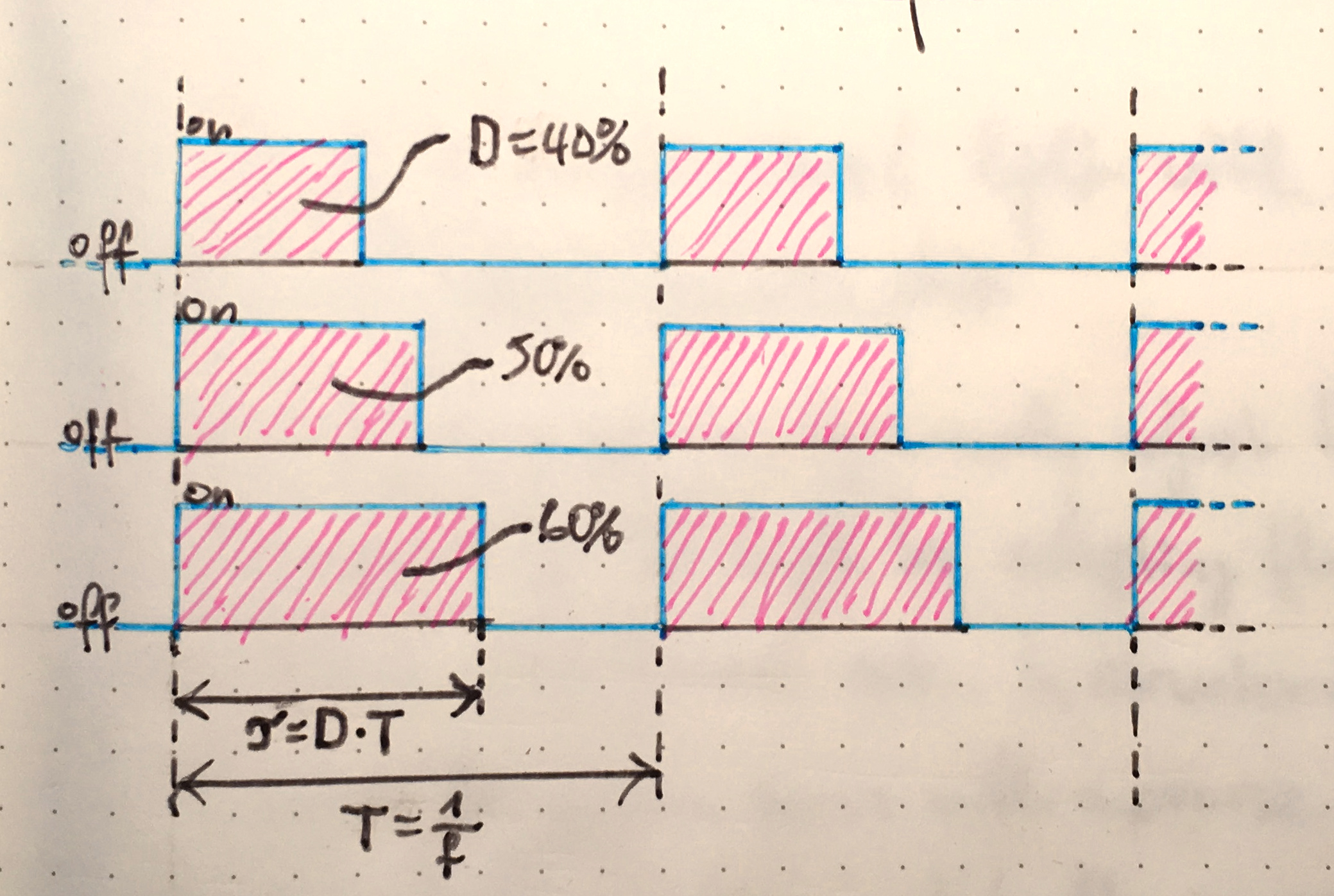
Waveforms of two PWM cycles at different duty cycles.

PWM works great if you have a dedicated PWM output on your microcontroller. It's extremely simple in both hardware and software. Unfortunately for us, controlling 32 channels with PWM is not that easy. Cheap microcontrollers only have a handful of hardware PWM outputs, so we'd either have to do everything in software, bit-banging our LED modulation, or we'd have to use a dedicated chip.

Doing PWM in software is both error-prone and slow. Since the maximum dynamic range of a PWM signal is limited by the shortest duty cycle it can do, software PWM being slow means it has poor PWM resolution at maybe 8 bits at most. Poor color resolution is not a problem if all you're doing is to fade around the HSV rainbow, but for ambient lighting where you really want to control the brightness down to a faint shimmer you need all the color resolution you can get.

If you rule out software PWM, what remains are dedicated hardware PWM controllers. Most of these have either of three issues:

  • They're expensive
  • They don't have generous PWM resolution either (12 bits if you're lucky)
  • They're meant to drive small LEDs such as a 7-segment display directly and you can't just hook up a MOSFET to their output

This means we're stuck in a dilemma between two poor solutions if we'd want to do PWM. Luckily for us, PWM is not the only modulation in town.

Binary Code Modulation

PWM is the bread-and-butter of the maker crowd. Everyone and their cat is doing it and it works really well most of the time. Unbeknownst to most of the maker crowd, there is however another popular modulation method that's mostly used in professional LED systems: Enter *Binary Code Modulation* (BCM).

BCM is to PWM sort of what barcodes are to handwriting. While PWM is easy to understand and simple to implement if all you have is a counter and an IO pin, BCM is more complicated. On the other hand, computers can do complicated and BCM really shines in multi-channel applications.

Similar to PWM, BCM works by turning on and off the LED in short periods fast enough to make your eye perceive it as partially on all the time. In PWM the channel's brightness is linearly dependent on its duty cycle, i.e. the percentage it is turned on. In PWM the duty cycle D is the total period T divided by the on period T_on. The issue with doing PWM on many channels at once is that you have to turn off each channel at the exact time to match its duty cycle. Controlling many IO pins at once with precise timing is really hard to do in software.

BCM avoids this by further dividing each period into smaller periods which we'll call bit periods and splitting each channel's duty cycle into chunks the size of these bit periods. The amazingly elegant thing in BCM now is that as you can guess from the name these bit periods are weighted in powers of two. Say the shortest bit period lasts 1 microsecond. Then the second-shortest bit period is 2 microseconds and the third is 4, the fifth 8, the sixth 16 and so on.

A visualization of BCM at different duty cycles.
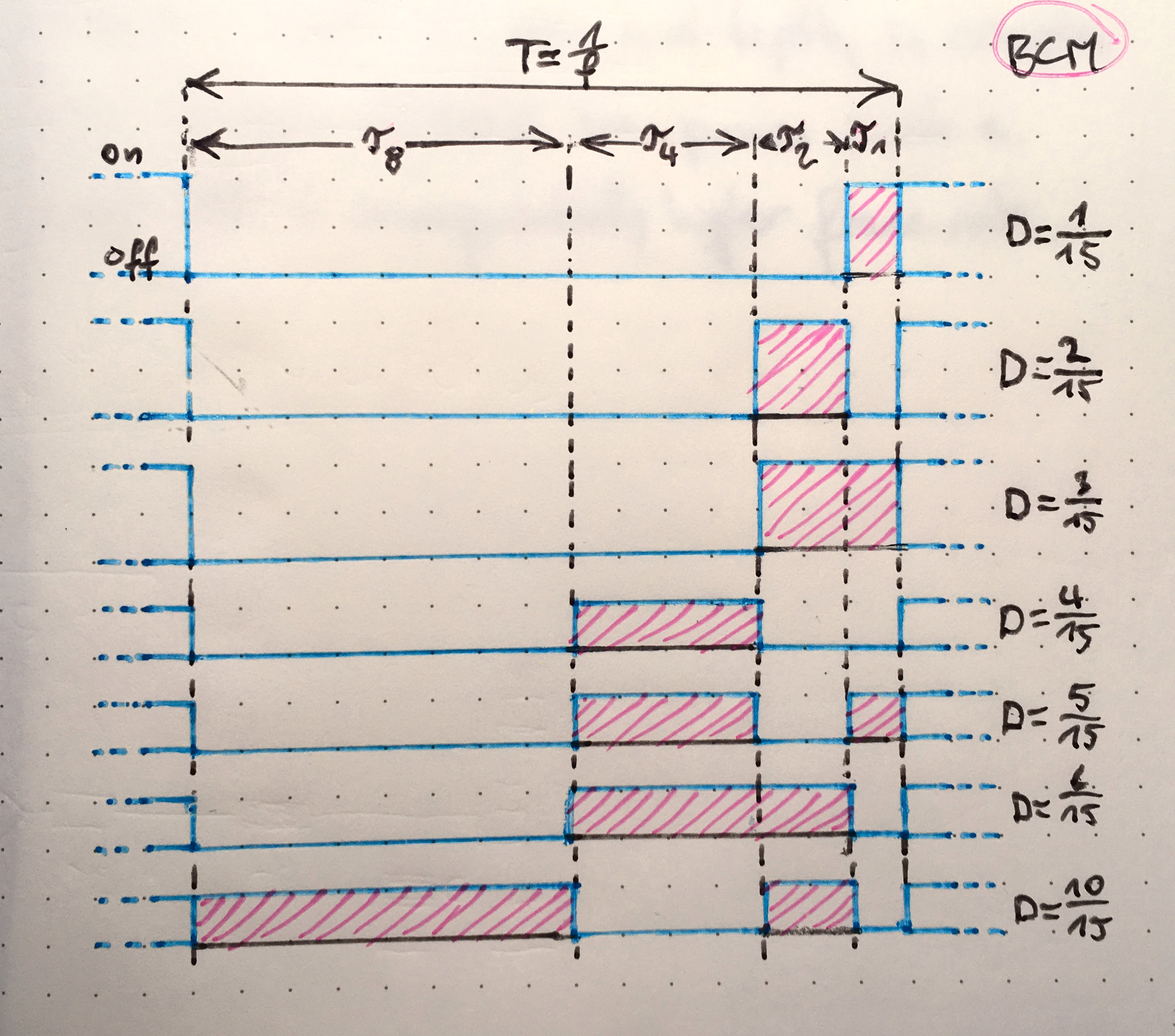
Waveforms of a single 4-bit BCM cycle at different duty cycles. This BCM can produce 16 different levels.

Staggered like this, you turn on the LED for integer value of microseconds by turning it on in the bit periods corresponding to the binary bits of that value. If I want my LED to light for 19 microseconds every period, I turn it on in the 16 microsecond bit period, the 2 microsecond bit period and the 1 microsecond bit period and leave it off for the 4 and 8 mircosecond bit periods.

Now, how this is better instead of just more complicated than plain old PWM might not be clear yet. But consider this: Turning on and off a large number of channels, each at its own arbitrary time is hard because doing the timing in software is hard. We can't use hardware timers since we only have two or three of those, and we have 32 channels. However, we can use one hardware timer to trigger a really cheap external latch to turn on or off the 32 channels all at once. With this setup, we can only controll all channels at once, but we can do so with very precise timing.

All we need to do is to set our timer to the durations of the BCM bit periods, and we can get the same result as we'd get with PWM with only one hardware timer and a bit of code that is not timing-critical anymore.

Applications of Binary Code Modulation

BCM is a truly wondrous technique, and outside of hobbyist circles it is in fact very widely known. Though we're using it to control just 32 channels here, you can do much more channels without any problems. The most common application where BCM is invariably used is any kind of LED screen. Controlling the thousands and thousands of LEDs in an LED screen with PWM with a dedicated timer for each LED would not be feasible. With BCM, all you need to dedicate to a single LED is a flipflop (or part of one if you're multiplexing). In fact, there is a whole range of ICs with no other purpose than to enable BCM on large LED matrices. Basically, these are a high-speed shift register with latched outputs much like the venerable 74HC595, only their outputs are constant-current sinks made so that you can directly connect an LED to them.

Running BCM on LED tape

In our case, we don't need any special driver chips to control our LED tape. We just connect the outputs of a 74HC595 shift register to one MOSFET each, and then we directly connect the LED tape to these MOSFETs. The MOSFETs allow us to drive a couple of amps into the LED tape from the weak outputs of the shift register.

The BCM timing is done by hooking up two timer channels of our microcontroller to the shift registers strobe and reset inputs. We set the timer to PWM mode so we can generate pulses with precise timing. At the beginning of each bit period, a pulse will strobe the data for this bit period that we shifted in previously. At the end of the bit period, one pulse will reset the shift register and one will strobe the freshly-reset zeros into the outputs.

From left to right, we see the STM32, one of the shift
    registers, and the LEDs and MOSFETs. The LED tape is driven to ground by the MOSFETs, which are in turn directly
    driven from the shift register outputs. The shift register is wired up to the STM32 with its clock and data
    inputs on SCK and MOSI and its RESET and STROBE inputs on channel 2 and 3 of timer 1.
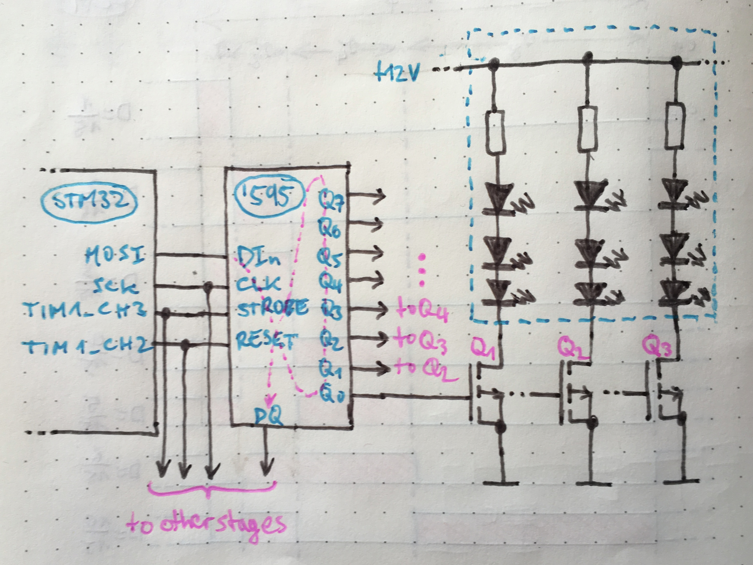
The schematic of a single output of this LED driver. Multiple shift register stages can be cascaded.

Our implementation of this system runs on an STM32F030F4P6, the smallest, cheapest ARM microcontroller you can get from ST. This microcontroller has only 16kB of flash and 1kB of RAM, but that's plenty for our use. We use its SPI controller to feed the modulation data to the shift registers really fast, and we use two timer channels to control the shift registers' reset and strobe.

We can easily cascade shift registers without any ill side-effects, and even hundreds of channels should be no problem for this setup. The only reason we chose to stick to a 32-channel board is the mechanics of it. We thought it would be easier to have several small boards instead of having one huge board with loads of connectors and cables coming off it.

The BOM cost per channel for our system is 3ct for a reasonable MOSFET, about 1ct for one eighth of a shift register plus less than a cent for one resistor between shift register and MOSFET. In the end, the connectors are more expensive than the driving circuitry.

Hardware design

From this starting point, we made a very prototype-y hardware design for a 32-channel 12V LED tape driver. The design is based on the STM32F030F4P6 driving the shift registers as explained above. The system is controlled through an RS485 bus that is connected up to the microcontroller's UART using an MAX485-compatible RS485 transceiver. The LED tape is connected using 9-pin SUB-D connectors since they are cheap and good enough for the small current of our short segments of LED tape. The MOSFETs we use are small SOT-23 logic-level MOSFETs. In various prototypes we used both International Rectifier's IRLML6244 as well as Alpha & Omega Semiconductor's AO3400. Both are good up to about 30V/5A. Since we're only driving about 2m of LED tape per channel we're not going above about 0.5A and the MOSFETs don't even get warm.

Switching nonlinearities

During testing of our initial prototype, we noticed that the brightness seemed to jump around when fading to very low values. It turned out that our extremely simple LED driving circuit consisting of only the shift register directly driving a MOSFET, which in turn directly drives the LED tape was maybe a little bit too simple. After some measurements it turned out that we were looking at about 6Vpp of ringing on the driver's output voltage. The picture below is the voltrage we saw on our oscilloscope on the LED tape.

Strong ringing on the LED voltage waveform edge at about
        100% overshoot during about 70% of the cycle time.
Bad ringing on the LED output voltage caused by wiring inductance. Note that the effect on the actual LED current is less bad than this looks since the LED's V/I curve is nonlinear.

Dynamic switching behavior: Cause and Effect

A bit of LTSpice action later we found that the inductance of the few metres of cable leading to the LED tape is the likely culprit. The figure below is the schematic used for the simulations.

The LTSpice schematic of one output of the driver,
    taking into account the shift register's output ESR and the wiring ESL.
The schematic of the simulation in LTSpice

As tested, the driver does not include any per-output smoothing so the ~.5A transient on each BCM cycle hits the cable in full. Combined with the cable inductance, this works out to a considerable lag of the rising edge of the LED current, and bad ringing on its falling edge. Below is the voltage on the LED output from an LTSpice simulation of our driver.

The result of the LTSpice simulation of our driver output. The LED
    current shows similar ringing to what we measured using the oscilloscope. Interestingly, the gate voltage shows
    strong ringing, too.
The result of our LTSpice simulation. This simulation assumes 1µH of wiring inductance and 50Ω of output impedance on the part of the shift register. The ringing at the gate visible in the gate voltage graph is due to feed-through of the ringing at the output through the MOSFET's parasitic Cgd.

We were able to reduce the rining and limit the effect somewhat by putting a 220Ω series resistor in between the shift register output and the MOSFET gate. This resistor forms an RC circuit with the MOSFET's nanofarad or two of gate capacitance. The result of this is that the LED current passing the wire's ESL rises slightly more slowly and thus the series inductance gets excited slightly less, and the overshoot decreases. Below is a picture of the waveform with the damping resistor in place and a picture of our measurement for comparison. The resistor values don't agree perfectly since the estimated ESL and stray capacitance of the wiring is probably way off.

Weak ringing on the LED voltage waveform edge at about 30%
    overshoot during about 20% of the cycle time.
Adding a resistor in front of the MOSFET gate to slow the transition damped the ringing somewhat, but ultimately it cannot be eliminated entirely. Note how you can actually see the miller plateau on the trailing edge of this signal.
The result of the LTSpice simulation of our driver output with an
    extra 100 Ohms between shift register output and MOSFET gate. Similar to the oscilloscope measurement the
    ringing is much reduced in its amplitude.
The LTSpice simulation result with the same parameters as above but with an extra 100Ω between the shfit register's output and the MOSFET's gate.

A side effect of this fix is that now the effective on-time of the LED tape is much longer than the duty cycle at the shift register's output at very small duty cycles (1µs or less). This is caused by the MOSFET's miller plateau. For illustration, below is a graph of both the excitation waveform (the boxy line) and the resulting LED current (the other ones) both without damping (top) and with 220Ω damping (bottom). As you can see the effective duty cycle of the LED current is not at all equal to the 50% duty cycle of the excitation square wave.

The result of an LTSpice simulation of the LED duty cycle without and
    with damping. Dampening widens the LED current waveform from 50% duty cycle with sharp edges to about 80% duty
    cycle with soft edges.
Simulated LED duty cycle with and without damping. The damping resistance used in this simulation was 220Ω.
The gate voltages in the spice simulation above. The undamped
    response shows sharp edges with the miller plateau being a barely noticeable step, but with strong ringing on
    the trailing edge. The damped response shows RC-like slow-edges, but has wide miller plateaus on both edges
    adding up to about 50% of the pulse width.
The MOSFET gate voltage from the simulation in the figure above. You can clearly see how the miller plateau (the horizontal part of the trace at about 1V) is getting much wider with added damped, and how the resulting gate charge/discharge curve is not at all that of a capacitor anymore.

In conclusion, we have three major causes for our calculated LED brightness not matching reality:

  • Ringing of the equivalent series inductance of the wiring leading up to the LED tape
  • Miller plateau lag
  • The damping resistor and the MOSFET gate forming an RC filter that helps with wire ESL ringing but worsens the miller plateau issue and deforms the LED current edges.

Added up, these three effects yield a picture that agrees well with our simulations and measurements. The overall effect is neglegible at long period durations (>10µs), but gets really bad at short period durations (<1µs). The effect is non-linear, so correcting for it is not as simple as adding an offset.

Measuring LED tape brightness

In order to correct for the nonlinearities mentioned above, we decided to implement a lookup table mapping BCM period to actual timer setting. That is, each row of the table contains the actual period length we need to set the microcontroller's timer to in order to get our intended brightness steps.

To calibrate our driver, we needed a setup for reproducible measurement of the relative brightness of our LED tape at different settings. Absolute brightness is not of interest to us as the eye can't perceive it. To perform the calibration, the LED driver is set to enable each single BCM period in turn, i.e. brightness values 1, 2, 4, 8, 16 etc.

The setup we used to measure the LED tape's brightness consists of a bunch of LED tape stuck into a tin can for shielding against both stray light and electromagnetic interference and a photodiode looking at the LED tape. We used the venerable BPW34 photodiode in our setup as I had a bunch leftover from another project and because they are quite sensitive owing to their physically large die area.

The led measurement setup consists of several PCBs and a
    breadboard linked with a bunch of wires and a big tin can to shield the LEDs and the photodiode. A large sub-D
    connector is put into the top of the tin can as a feed-through for the LED tape's control signals and the
    photodiode signal. In the background the control laptop is visible.
The LED brighness measurement setup. The big tin can contains a bunch of LED tape and the photodiode. The breadboard on the right is used for the photodiode preamplifier and for jumpering around the LED tape's channels. The red board next to it is the buspirate used as ADC. The board on the bottom left is a TTL-to-RS485 converter and the board in the middle is the unit under test.

The photodiode's photocurrent is converted into a voltage using a very simple transimpedance amplifier based around a MCP6002 opamp that was damped into oblivion with a couple nanofarads of capacitance in its feedback loop. The MCP6002 is a fine choice here since I had a bunch and because it is a CMOS opamp, meaning it has low bias current that would mess up our measurements. For many applications, opamp bias current is not a big issue but when using the opamp to directly measure very small currents at its input it quickly swamps out the signal for most BJT-input types.

The transimpedance amplifier's output is read from the computer using the ADC input of a buspirate USB thinggamajob. In general I would not recommend the buspirate as a tool for this job since it's ADC is not particularly good and it's programming interface is positively atrocious, but it was what I had and it beat first wiring up one of the dedicated ADC chips I had in my parts bin.

The computer runs a small python script cycling the LED tape through all its BCM period settings and taking a brightness measurement at each step. Later on, these measurements can be plotted to visualize the resulting slope's linearity, and we can even do a simulation of the resulting brightness for all possible control values by just adding the measured photocurrents for a certain BCM setpoint just as our retinas would do.

A plot of the measured brightness of our LED tape for each BCM period. The brightness values are normalized to the value measured at the LSB setpoint (brightness=1/65535). Ideally, this plot would show a straight line with slope 1. Obviously, it doesn't. The bend in the curve is caused by the above-mentioned duty cycle offset adding an offset to all brightness values. Shown is both the raw data (light), which has essentially zero measurement error and a linear fit (dark). The plot is in log-log to approximate how the human eye would perceive brightness, i.e. highly sensitive at low values but not very sensitive at all at large values.

While it would be possible to fully automate the optimization of BCM driver lookup tables, we needed only one and in the end I just sat down and manually tweaked the ideal values we initially calculated until I liked the result. You can see the resulting brightness curve below.

Calculated brightness curve for the uncorrected BCM setup. As you can see, at low setpoints the result is about as smooth as sandpaper, which is well in line with our observations. At high setpoints the offset gets swamped out and the nonlinearity in the low bits is not visible anymore.
Brightness curve for the corrected BCM setup extrapolated using actual measurements. Looks as buttery smooth in real life as it does in this plot.

Controlling the driver

Now that our driver was behaving linear enough that you couldn't see it actually wasn't we needed a nice way to control it from a computer of our choice. In the ultimate application (our staircase) we'll use a raspberry pi for this. Since we already settled on an RS485 bus for its robustness and simplicity, we had to device a protocol to control the driver over this bus. Here, we settled on a simple, COBS-based protocol for the reasons I wrote about in How to talk to your microcontroller over serial.

To address our driver nodes, we modified the Makefile to build a random 32-bit MAC into each firmware image. The protocol has only five message types:

  1. A 0-byte ping packet, to which each node would reply with its own address in the first 100ms after boot. This can be used to initially discover the addresses of all nodes connected to the bus. You'd spam the bus with ping packets, and then hit reset on each node in turn. The control computer would then receive each device's MAC address as you hit reset.
  2. A 4-byte address packet that says which device that the following packet is for. This way of us using the packet length instead of a packet type field is not particularly elegant, but our system is simple enough and it was easy to implement.
  3. A 64-byte frame buffer packet that contains 16 bits of left-aligned brightness data for every channel
  4. A one-byte get status packet that tells the device to respond with...
  5. ...a 27-byte status packet containing a brief description of the firmware (version number, channel count, bit depth etc.) as well as the device's current life stats (VCC, temperature, uptime, UART frame errors etc.).

Wrapped up in a nice python interface we can now easily enumerate any drivers we connect to a bus, query their status and control their outputs.

Conclusion

A picture of the LED driver schematic
The LED driver schematic
A picture of the LED driver PCB layout
The LED driver PCB layout

Putting some thought into the control circuitry and software, you can easily control large numbers of channels of LEDs using extremely inexpensive driving hardware without any compromises on dynamic range. The design we settled on can drive 32 channels of LED tape with a dynamic range of 14bit at a BOM cost of below 10€. All it really takes is a couple of shift registers and a mildly bored STM32 microcontroller.

Get a PDF file of the schematic and PCB layout here or download the CAD files and the firmware sources from github. You can view the Jupyter notebook used to analyze the brightness measurement data here.